2014-05-06
The new charging system is now up and running, what I noticed is that the solar panel deliveres the highest voltage which will lead to a situation that even if I connect the shore cable to 220 volts, a sunny day the solar panel will still be the source charging the batteries, this is not a situation I prefer so I will install a switch to "cancel out" charging from the solar panel, to favour the more powerful shore power, otherwise the system runs great. Another thing I noticed is that if the hirearki will never stop charging any battery, for example the house batteries, they are first fully chaarged, when the battery separator declares it fully charged and opens up to start charging the engine start battery, it does not inihibit the charging to the house battery, so at the end, the system will charge all three battery banks together, this will most likel lead to that charging will always take place since they are together more than 500 Amphours.
I now declare this project implemented, its been great fun, elecrical installation are fun to make.
2014-04-04
Every day is one step forward, o also today.
Today I routed the 10 mm2 charging cables from the Alternator and the Starting
Battery to the electriacl compartment, I crimped the terminal ends and protected
them with melting tubes, it took a while but its all worth the extra effort
in the long run.
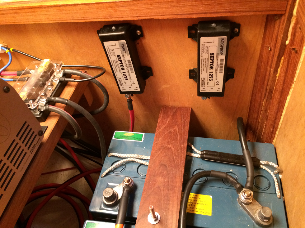
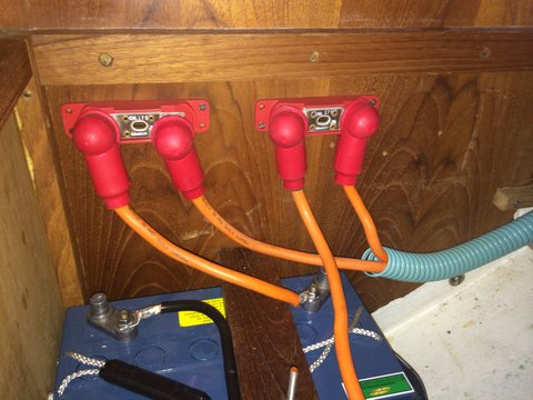
On the picture you can see the two Battery Priority relays. When the two house batteries are fully charged, the start battery is charged, when it is fully charged, the windlass/bow thruster is charged. To the far left you can see the Charging Bus with negative bar at the right and positive bar far to the left. The blue cable is the solar charger positive lead (150 W). Red is shore power charger (40 Amps).
2014-03-31
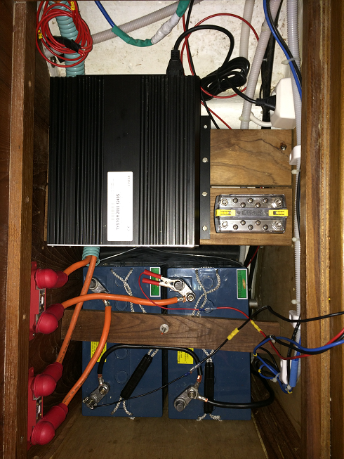
Yesturday I installed the Tystor 25 Amp Shore Charger, installed it as so outboard as possible so the batteries could be removed, it was tight, I want to keep the area roomy because if it becomes to tight it will be hard to keep it organized and ship-shape.
Next to the charger I installed the Charging Bus, to it all the charging
sources will be routed and from it, directly the house batteries and via Septors,
first to the engine battery and next the windlass/side power battery.
Current IN will be installed on the larger posts
and Current OUT on the screws in the centre.
The Charging Bus is built up of two buses, and the "upper" bus on
the picture will become the positive side and the "lower" bus the
negative.

2014-03-30
I have decided to upgrade and reconfigure my battery charging installation.
Today I have these hardwares:
A 15 Amp shore charger (will be replaced)
A 35 Amp Engine Alternator (will be replaced)
2 ea 75 W solar panels
1 90 Amp/hour Starting battery gel type
2 115 Amp/hour House Battries gel type
1 90 Amp/hour Windlass/Side Power battery gel type
These are the new hardware that will be installed:
A 25 Amp Tystor Shore Power
A 115 Amp Engine Alternator
2 ea 75 Amp Septor Charging Distributors
The thing is also that I am not all that happy with the hirearcy of how
the charging takes place.
As it is right now is ts that the Windlass/Side Power battery is only charged
by the solar panels and only when the house batteries are fully charged.
When completed the hirearcy will be very simple, whatever is charging (decided
by the highest voltage) will charge in order:
First the engine battery
Second the house batteries
And last the Windlass/Side Power battery
My thinkin is that usually the chargers will not compete, except for the solar power but they are the waakest so I dont bother about them whenever either the engine is runnning or if on shore power. Under sail the solar panels will charge the batteries in the sequence mentioned.
Here is a link to a pdf over the layout.
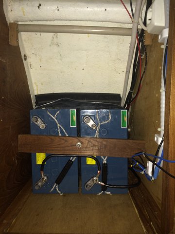
I did also reposition the batteries, to side bye side and to a little lower position. This also to make roo for the larger shore charger.
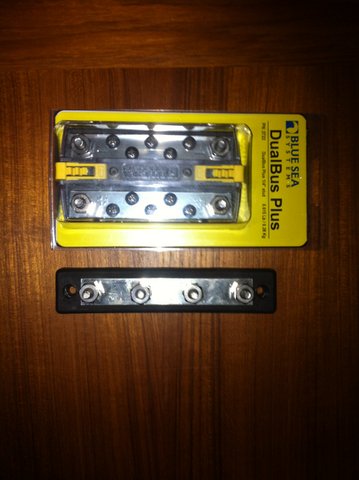
A picture of the two 150 Amp Current Limiters
In the new installation I will use Blue Sea System hardwares, the larger one as a Positive Feeder Bus and the smaller as a Negative Feeder Bus